
Arduino Project Series
Physical computing projects
Arduino & P5.js
February 2024 – March 2024
Individual Projects
HCDE 439
Project #3 Demo: Arduino, ultrasonic sensor & DC motor with a mini fan
Project #1: Don’t Open That Door
Concept
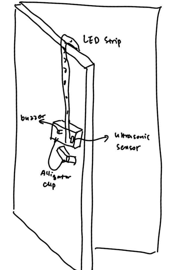
I’ve experienced living with roommates who are less aware of my personal boundary. For example, some of them would just randomly open my bedroom door without knocking or asking for permission. The others would silently stand outside of my door to eavesdrop on my conversation. The unpleasant experience living with these people motivated me to design and build a system that alerts me when someone’s approaching my bedroom. Once this system is connected to power, the LED strip lights up and functions as a light source and decorative component. If someone approaches my bedroom and is within 50 centimeters of distance from my door, the LED strip will blink and alert the person inside the room. If the person outside touches the door handle, then a buzzer will make a beeping sound indicating that someone’s trying to enter the room.
Materials
Door handle & aluminum foil (for capacitive sensing)
Buzzer (for making beeping sound)
Ultrasonic sensor (for detecting distance)
LED strip (to warn myself that someone is approaching)
12V power supply (for LED strip)
Alligator clips
Cardboard & tape (for prototyping)
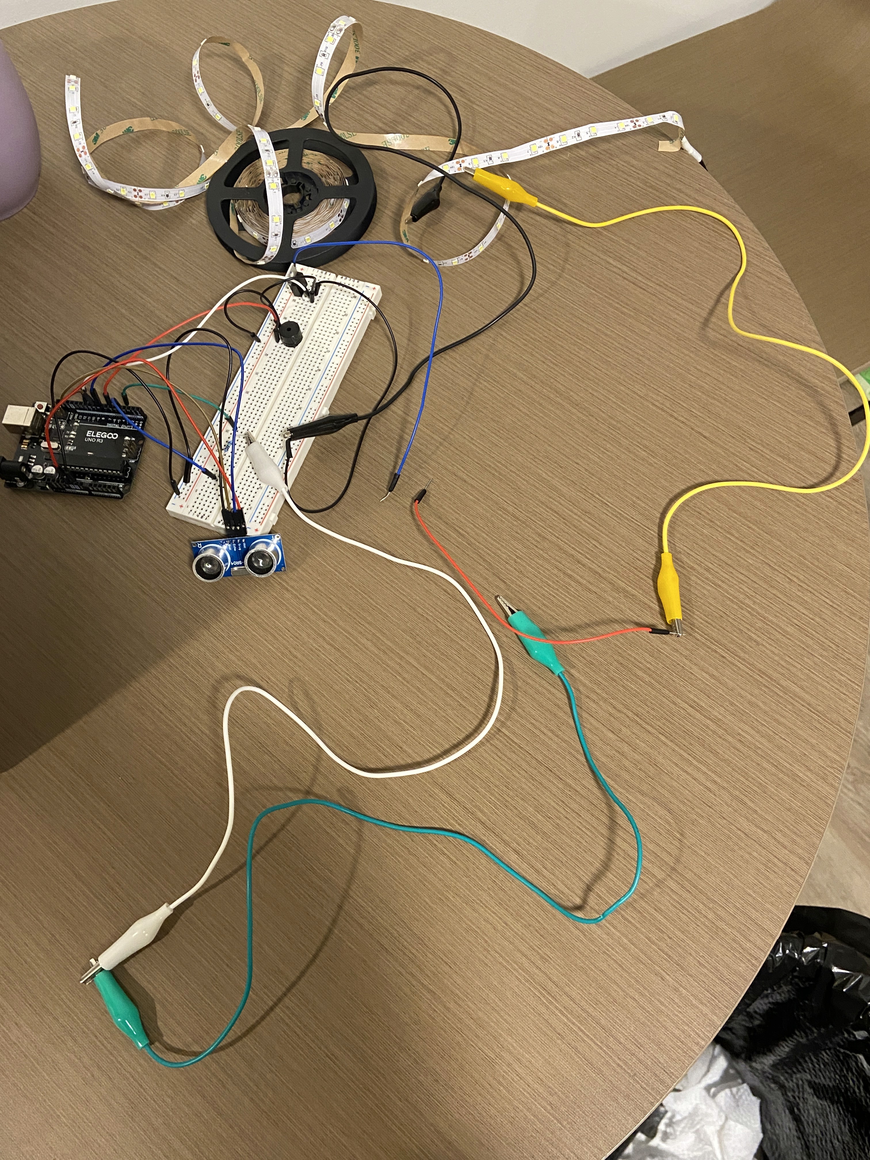
Implementation: Ultrasonic Sensor & LED Strip
For building the part where an LED strip blinks when someone’s within 50 cm of distance from the door, I used an ultrasonic sensor as the input device and an LED strip and the output device. The ultrasonic sensor has 4 pins, where the Vcc pin is connected to the 5V power, the Gnd pin is connected to ground, the Trig pin is connected to pin 8 and the Echo pin is connected to pin 9. For the LED strip, it is connected to circuit using the alligator clips. A transistor is connected to pin 11 of the Arduino board so that I can write code to control the LED strip.
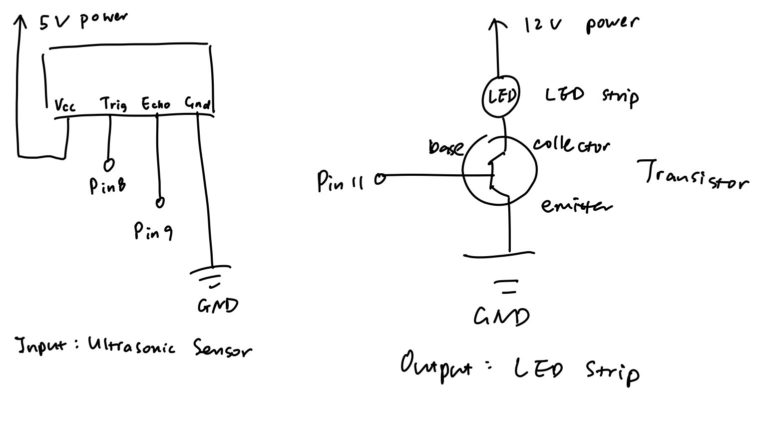
Schematic
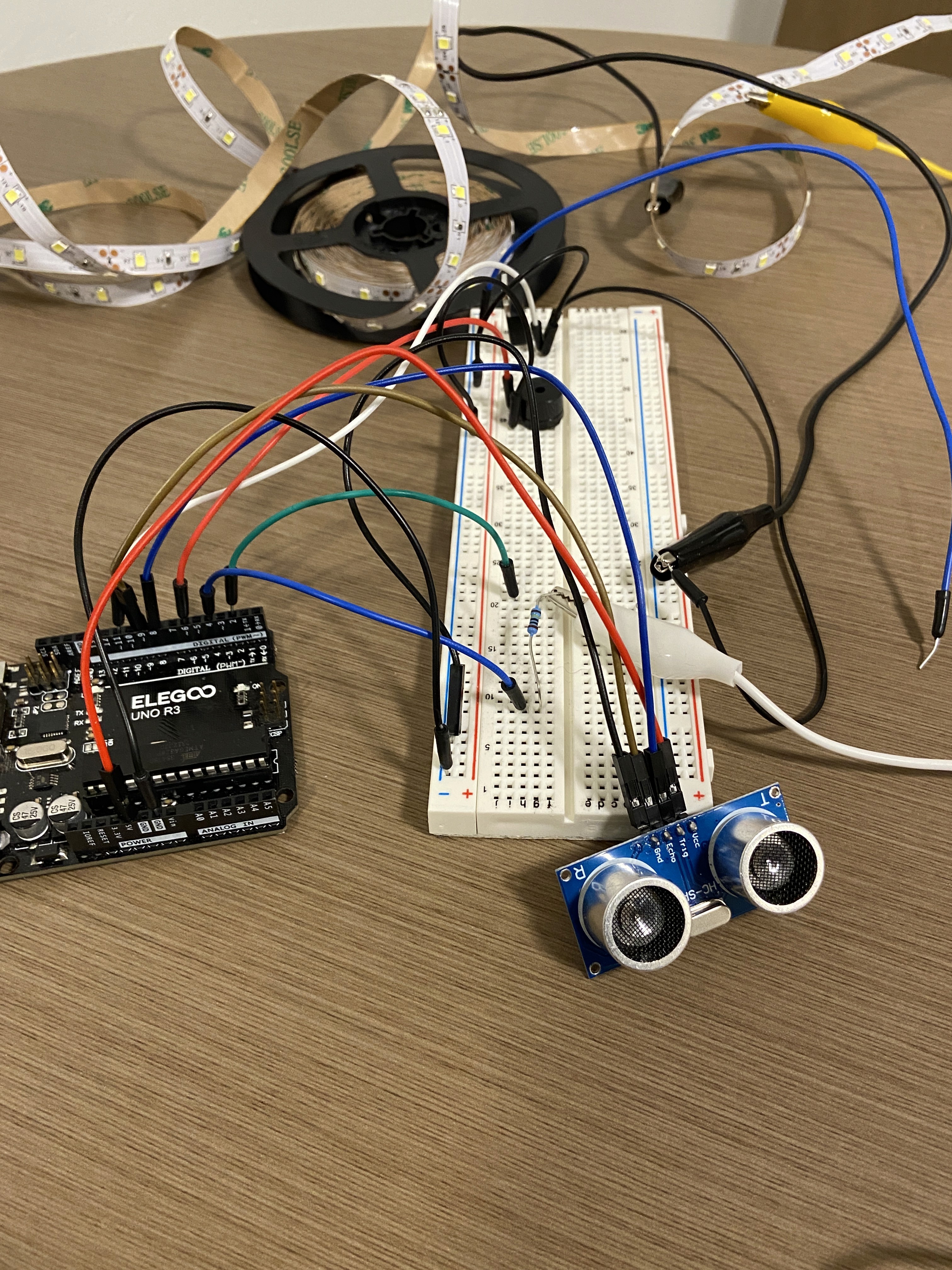
Circuit
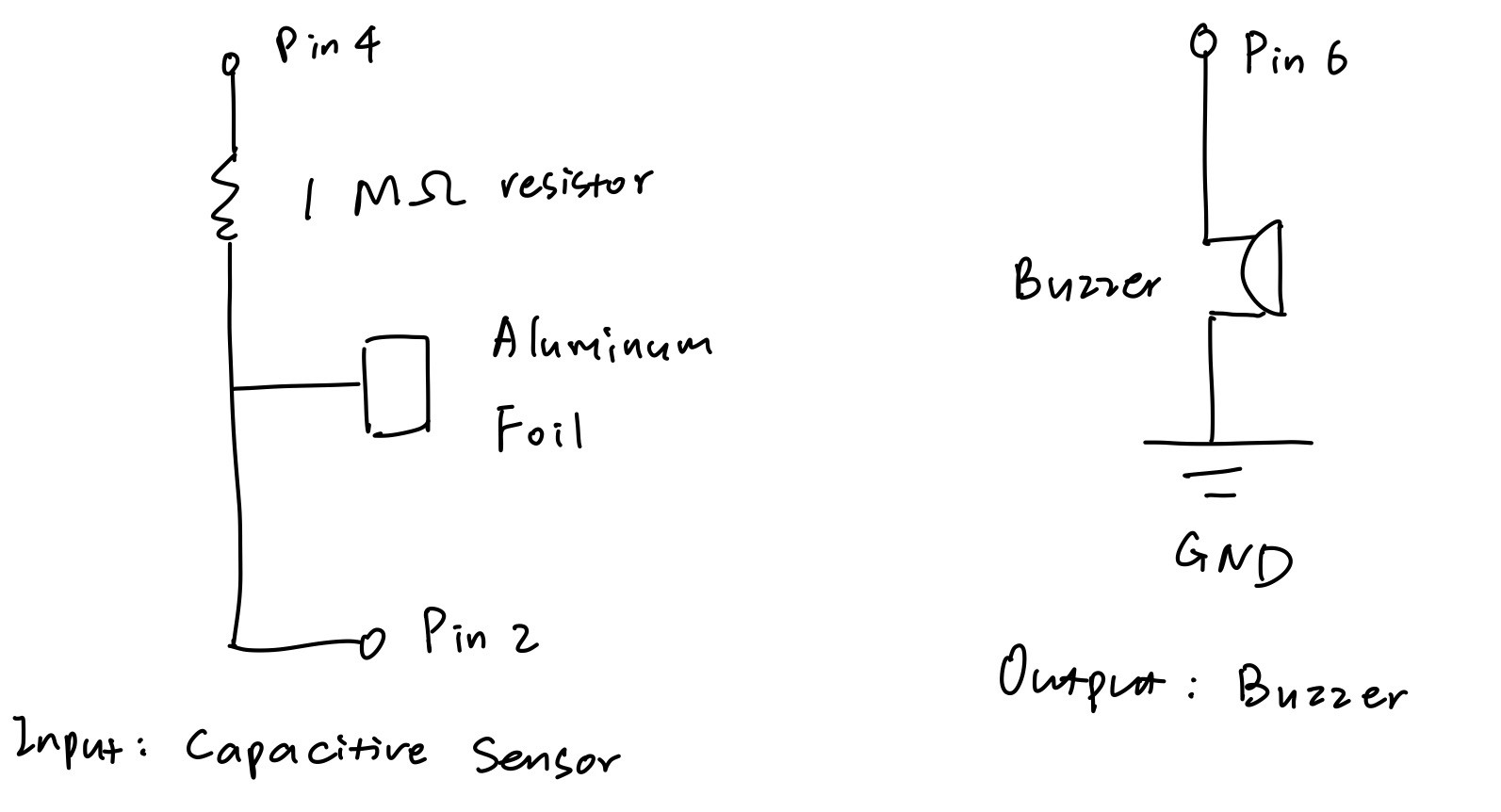
Implementation: Capacitive Sensor & Buzzer
Another important function of this product is that a buzzer makes beeping sound if someone touches the capacitive sensor (door handle). I first attempted to use the metal room handle itself to function as the capacitive sensing component, but the challenge I encountered was that the alligator clip was not able to open wide enough to grab my door handle. To address this issue, I wrapped some aluminum foil around the handle and had the alligator clip grab onto the foil instead of the handle. I taped the aluminum foil tightly with the handle so that the foil doesn’t move around when someone attempts to use the handle. A 1 megohm resistor is used between Arduino pin 2 and pin 4 because I would like the capacitive sensor to sense an absolute touch. After making sure that the capacitive sensor functions, I started to work with the buzzer, where I connected it to pin 6 and the ground. The buzzer is coded so that it makes beeping sound when a direct touch is sensed by the capacitive sensor. I created a box using cardboard and put the circuit inside and only left the ultrasonic sensor, the capacitive sensor, and the LED strip outside of the box. Finally, I connected the LED strip to the power supply to make it work. The box and the LED strip were taped on my door to make sure that they are fixed in place.
Schematic
Circuit
Code
For the Arduino code, I first included a capacitive sensor and an ultrasonic sensor library to work with the sensors. Then inside the void setup(), I initialized serial communication for debugging and initialized pin 11 (for LED strip) and pin 6 (for buzzer) as output. Inside the void loop(), I wrote code to first measure the distance from the ultrasonic sensor to the closest object that can be detected, and had the distance printed to Serial Monitor for debugging. If the distance detected is less than 50 cm, then the LED strip blinks in a pattern where it turns on for 35 ms and turns off for 35 ms. Then I wrote code to read the capacitance sensed by the capacitive sensor, and had it printed to the Serial Monitor for debugging. If the capacitance is greater than 2000, it means that a direct touch is sensed and the buzzer makes beeping sound.
#include // include the capasitive sensor library
          CapacitiveSensor cs_4_2 = CapacitiveSensor(4,2); // create a CapacitiveSensor instance. A 1 megohm
                                                              resistor is between pin 2 and pin 4.
resistor is between pin 2 and pin 4.
          #include "SR04.h" // include the ultrasonic sensor library, I found the library and example code for
                                the ultrasonic sensor called “SE04.h” from the ELEGOO website:
                                https://www.elegoo.com/blogs/arduino-projects/elegoo-uno-project-super-starter
                                kit-tutorial?_pos=12&_sid=6098200f4&_ss=r
the ultrasonic sensor called “SE04.h” from the ELEGOO website:
https://www.elegoo.com/blogs/arduino-projects/elegoo-uno-project-super-starter
kit-tutorial?_pos=12&_sid=6098200f4&_ss=r
#define TRIG_PIN 8 // set pin 8 to trigger
#define ECHO_PIN 9 // set pin 9 to echo
SR04 sr04 = SR04(ECHO_PIN,TRIG_PIN); // create an sr04 object for ultrasonic sensor
int distance; // create int variable distance
int buzzerPin = 6; // create int variable buzzerPin and set it to 6
int ledStripPin = 11; // create int variable ledStripPin and set it to 11
void setup() { // set up for serial communication and initialize pins
cs_4_2.set_CS_AutocaL_Millis(0xFFFFFFFF); // turn off autocalibrate on channel 1
Serial.begin(9600); // initialize serial communication for debugging
pinMode(ledStripPin, OUTPUT); // initialize LED strip pin as output
pinMode(buzzerPin, OUTPUT); // initialize the buzzer pin as output
}
          void loop() { // LED strip blinks if the closest object detected by the ultrasonic sensor is 50 cm or
                           less; buzzer makes beep sound if capacitive sensor is directly touched
less; buzzer makes beep sound if capacitive sensor is directly touched
            distance = sr04.Distance(); // measure distance from the ultrasonic sensor to the closest object
                                           that can be detected
that can be detected
Serial.print(distance); // print variable distance to serial monitor for debugging
Serial.println("cm"); // print "cm" to serial monitor and go to next line
delay(10); // wait for 10 ms
if (distance < 50) { // if the distance detected is less than 50 cm
digitalWrite(ledStripPin, HIGH); // turn on the LED strip
delay(35); // wait for 35 ms
digitalWrite(ledStripPin, LOW); // turn off the LED strip
delay(35); // wait for 35 ms
}
            long start = millis(); // create long variable start and set it to the number of milliseconds
                                       passed since the Arduino began running
passed since the Arduino began running
            long total1 =  cs_4_2.capacitiveSensor(30); // create long variable total1 and set it to the sensed
                                                            capacitance
capacitance
Serial.print(millis() - start); // check on performance in milliseconds
Serial.print("\t"); // tab character for debug window spacing
Serial.println(total1); // print sensor output
delay(50); // delay to limit data to serial port
if (total1 > 2000) { // if the sensed capacitance is greater than 2000
tone(buzzerPin, 1500, 60); // buzzer makes beep sound
}
}
Project #2: Web Communication (p5.js)
Concept
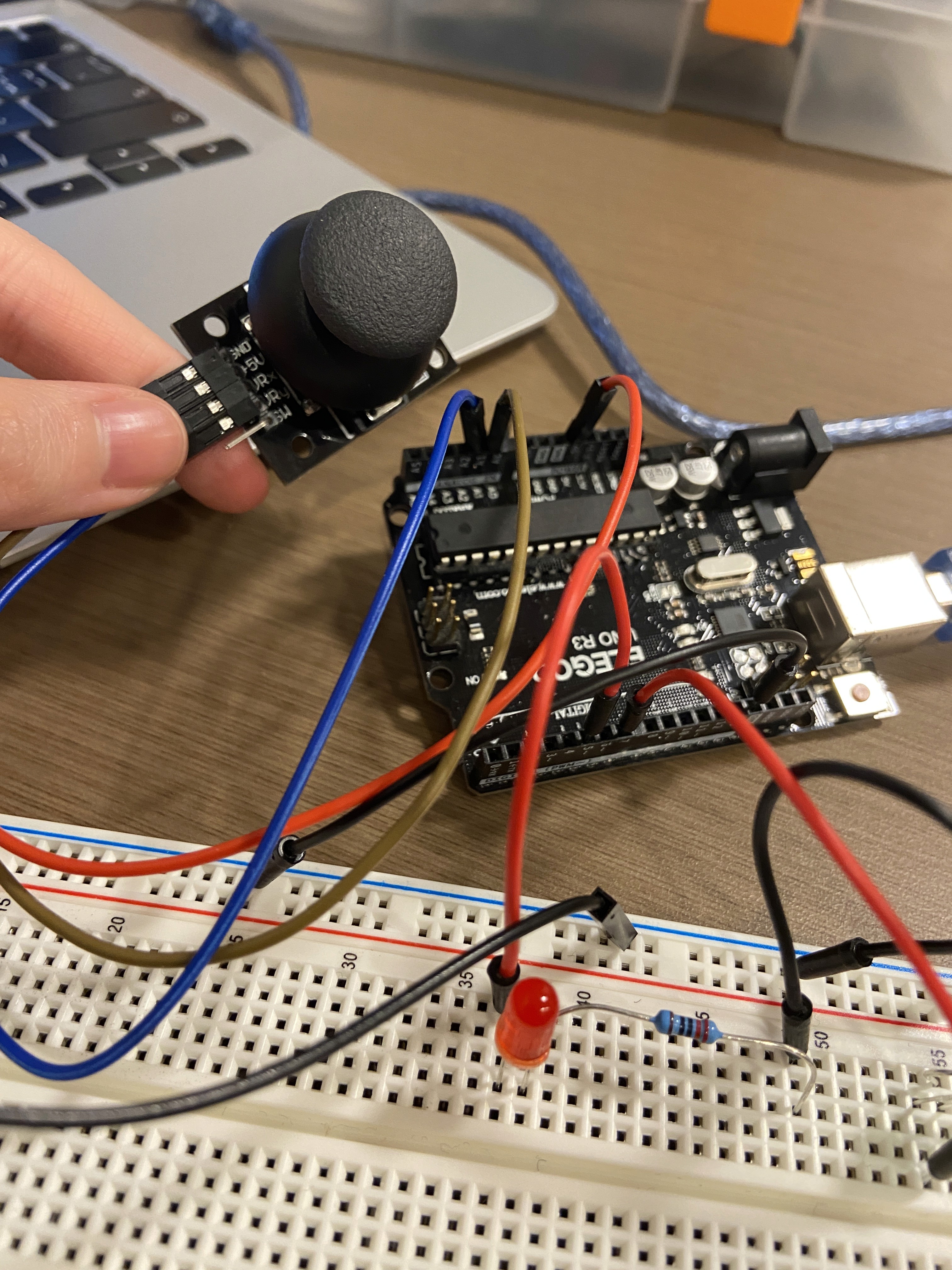
A canvas is connected to the input reads from a joystick using P5.js. Once the program stats running circles are displayed on the canvas and their positions and colors depends on the joystick input. If the circle shows up on the left side of the screen, it would be a red one; otherwise, it would be a green circle. Two LEDs are connected to the the Arduino board so that the green LED lights up if the circle on canvas is green and the red LED lights up if the circle is red.
Materials
Arduino board
Joystick
LEDs
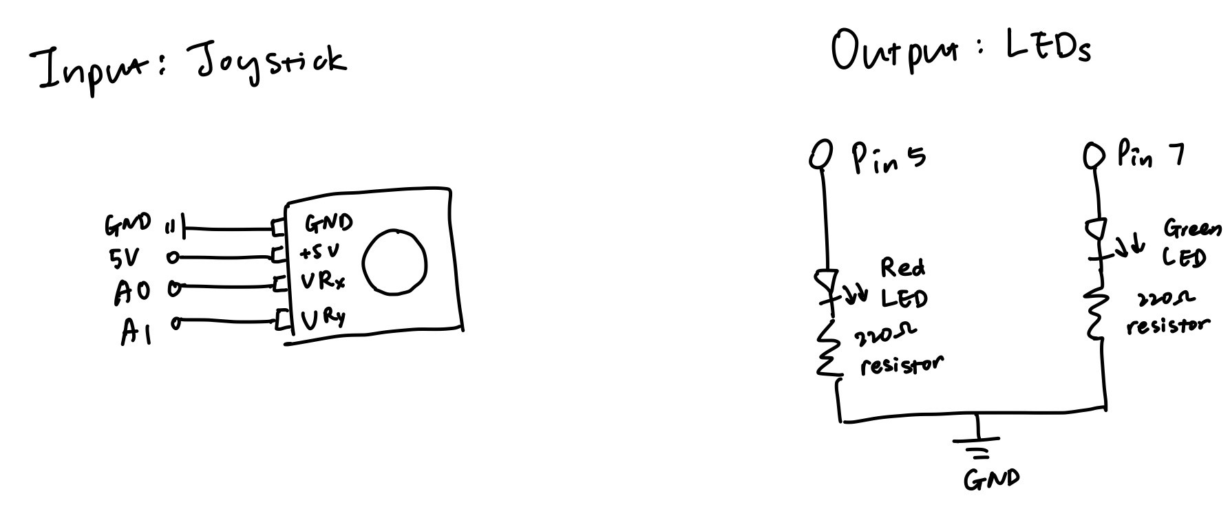
Implementation
Input Joystick: GND is connected to ground, +5V is connected to 5V power, VR_x is connected to A0, VR_y is connected to A1.
Output LEDs: The red LED is connected to Arduino pin 5, and the green LED is connected to Arduino pin 7.
Resistor choose: I used Ohm’s law to calculate the resistance of the resistor I should use: V=I*R. Since the voltage drop for red and green LEDs are 1.8 V, 5V-1.8V=20mA*R. Since 1A=1000mA, R=3.2V/0.02A, R=160Ω. However, there is no 160 Ω resistor in the kit, so I chose to use the 220 Ω ones because the way to make the current to be less than 20 mA is to choose a resistor with a slightly greater resistance.
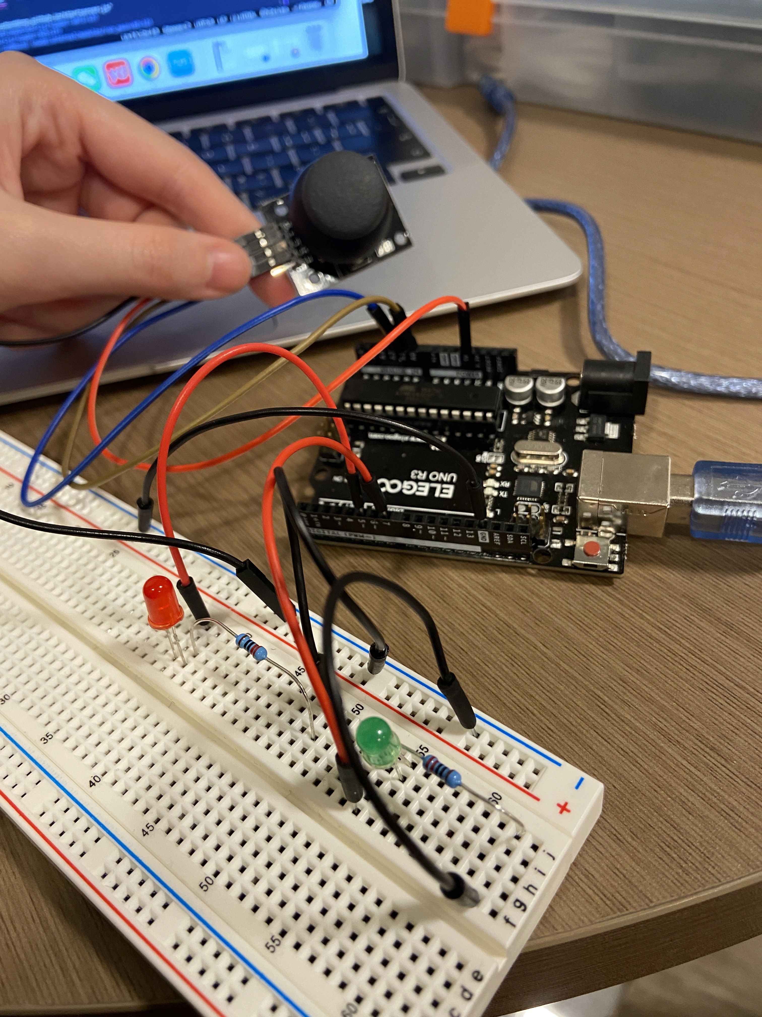
Circuit & circuit operation
Code: P5.js
const BAUD_RATE = 9600; // This should match the baud rate in Arduino sketch
let port, connectBtn; // Declare global variables
function setup() { // set up the canvas
setupSerial(); // Run our serial setup function (below)
createCanvas(windowWidth, windowHeight); // Create a canvas that is the size of our browser window
background("black"); // set the background color to black
}
function draw() {
const portIsOpen = checkPort(); // Check whether the port is open (see checkPort function below)
if (!portIsOpen) return; // If the port is not open, exit the draw loop
let str = port.readUntil("\n"); // Read from the port until the newline
if (str.length == 0) return; // If we didn't read anything, return
let array1 = str.trim().split(","); // store x and y values in array1 as str
            let valx = map(Number(array1[0]), 0, 1023, 0, windowWidth); // turn the x value str to a Number and
                                                                            map it to the window width, and
                                                                            store it to valx
map it to the window width, and
store it to valx
            let valy = map(Number(array1[1]), 0, 1023, 0, windowHeight); // turn the y value str to a Number
                                                                            and map it to the window height, and
                                                                            store it to valy
and map it to the window height, and
store it to valy
            if (valx < windowWidth/2) { // if valx is less than half of the window width (on the left hand side
                                            of the screen)
of the screen)
let c = color(255, 0, 0); // set c to red RGB code
fill(c); // use red to fill shape
circle(valx, valy, 50); // draw a circle where it's located at (valx, valy), has a diameter of 50
port.write(0); // send 0 to arduino
} else {
let c = color(0, 255, 0); // set c to green RGB code
fill(c); // use green to fill shape
              circle(valx, valy, 50);  // draw a circle where it's located at (valx, valy) and has a diameter
                                           of 50
of 50
port.write(1); // send 1 to arduino
}
}
// The three functions below are from the class example code.
// Three helper functions for managing the serial connection.
function setupSerial() {
port = createSerial();
// Check to see if there are any ports we have used previously
let usedPorts = usedSerialPorts();
if (usedPorts.length > 0) {
// If there are ports we've used, open the first one
port.open(usedPorts[0], BAUD_RATE);
}
// create a connect button
connectBtn = createButton("Connect to Arduino");
connectBtn.position(5, 5); // Position the button in the top left of the screen.
            connectBtn.mouseClicked(onConnectButtonClicked); // When the button is clicked, run the
                                                                 onConnectButtonClicked function
onConnectButtonClicked function
}
function checkPort() {
if (!port.opened()) {
// If the port is not open, change button text
connectBtn.html("Connect to Arduino");
// Set background to gray
background("gray");
return false;
} else {
// Otherwise we are connected
connectBtn.html("Disconnect");
return true;
}
}
function onConnectButtonClicked() {
// When the connect button is clicked
if (!port.opened()) {
// If the port is not opened, we open it
port.open(BAUD_RATE);
} else {
// Otherwise, we close it!
port.close();
}
}
Code: Arduino IDE
int x = A0; // declare int variable x and set it equal to A0
int y = A1; // declare int variable y and set it equal to A1
int xval = 0; // delare int xval and set it to 0
int yval = 0; // delare int xval and set it to 0
void setup() { // set up for serial communication and initialize pins
Serial.begin(9600); // initialize serial communication
Serial.setTimeout(10); // set the timeout for parseInt
pinMode(5, OUTPUT); // set pin 5 as OUTPUT
pinMode(7, OUTPUT); // set pin 7 as OUTPUT
}
        void loop() { // print the joystick x and y values to serial monitor, turn on and off the red LED if
                         the serial data received is 0, turn on and off the green LED if the serial data
                         received is 1
the serial data received is 0, turn on and off the green LED if the serial data
received is 1
xval = analogRead(x); // set xval equal to joystick x value
yval = analogRead(y); // set yval equal to joystick y value
Serial.print(xval); // print xval to serial monitor
Serial.print(","); // print "," to serial monitor
Serial.println(yval); // print yval to serial monitor and go to next line
delay (100); // wait for 100 ms
if (Serial.available() > 0) { // if there's serial data
int inByte = Serial.read(); // set int inByte to the serial data
if (inByte == 0) { // if int inByte is equal to 0
digitalWrite(5, HIGH); // turn on red LED
delay(50); // wait for 50 ms
digitalWrite(5, LOW); // turn off the red LED
}
if (inByte == 1) { // if int inByte is equal to 1
digitalWrite(7, HIGH); // turn on the green LED
delay(50); // wait for 50 ms
digitalWrite(7, LOW); // turn off the green LED
}
}
}
Project #3: Transistor-Controlled DC Motor
Concept
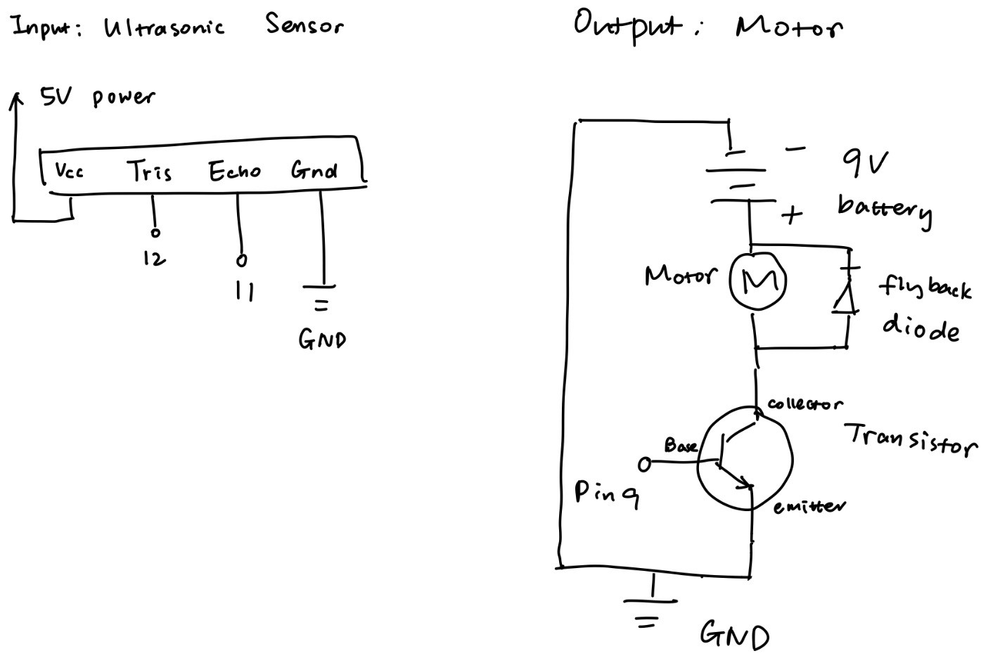
For this assignment, I used an ultrasonic sensor, a DC motor with a fan attached to it, a flyback diode, and an Arduino board. If the distance of the closest object detected by the ultrasonic sensor is less than 40 cm, then the motor spins.
Materials
Arduino board
Ultrasonic sensor
DC motor & mini fan
Transistor
Flyback diode
9V battery
Implementation
According to the DC motor datasheet (https://wiki-content.arduino.cc/documents/datasheets/DCmotor6_9V.pdf), when the power supply is 6 V, the max no load current is 280 mA. Since the battery in the circuit supplies 9 V (which is 1.5 times 6 V), then the current would be 1.5 * 280 mA = 420 mA, which is less than 600 mA, the max current that the transistor can handle.
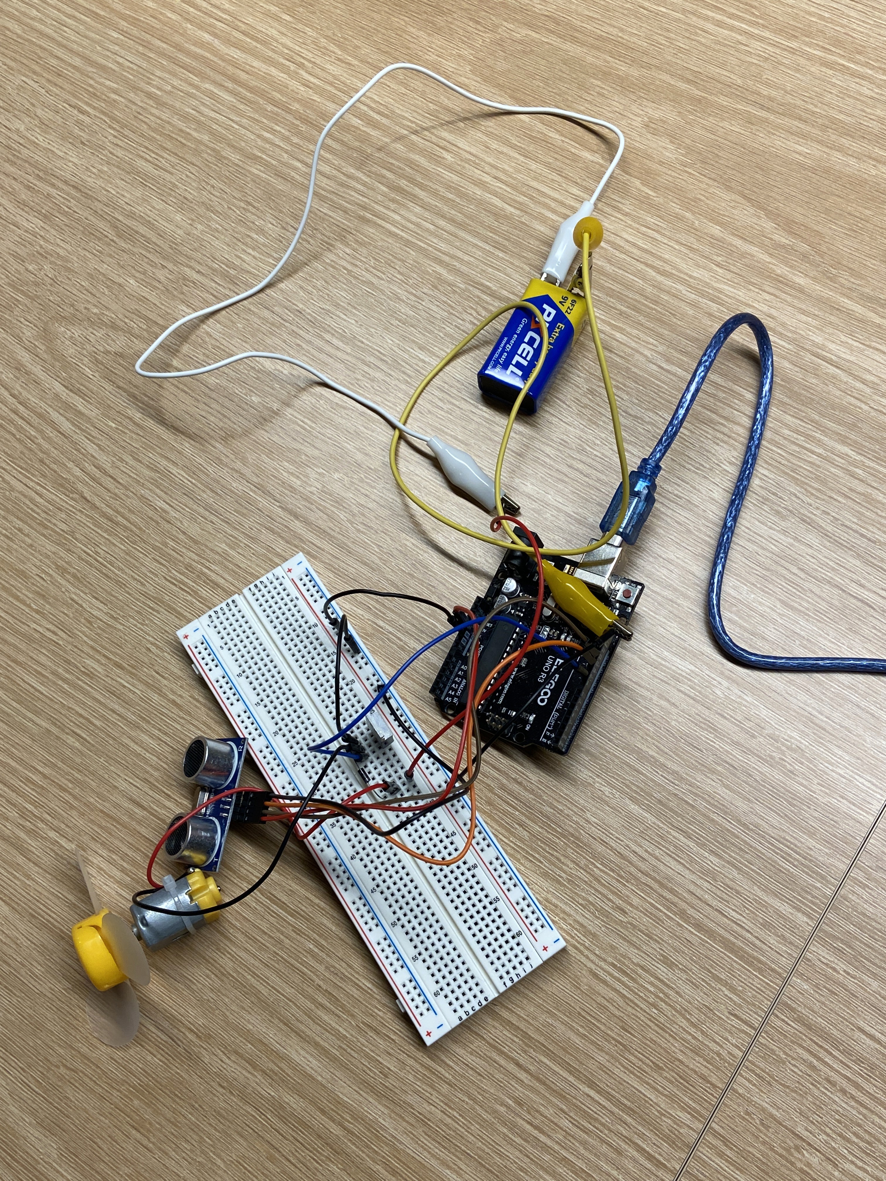
Circuit & circuit operation
Code
        // I found the library and example code for the ultrasonic sensor called “SE04.h” from the ELEGOO
           website: https://www.elegoo.com/blogs/arduino-projects/elegoo-uno-project-super-starter-kit-tutorial
           _pos=12&_sid=6098200f4&_ss=r
website: https://www.elegoo.com/blogs/arduino-projects/elegoo-uno-project-super-starter-kit-tutorial
_pos=12&_sid=6098200f4&_ss=r
#include "SR04.h" // include the ultrasonic sensor library
#define TRIG_PIN 12 // set pin 12 to trigger
#define ECHO_PIN 11 // set pin 11 to echo
SR04 sr04 = SR04(ECHO_PIN,TRIG_PIN); // create an sr04 object for ultrasonic sensor
int distance; // create int variable distance
const int DISTANCE_THRESHOLD = 40; // set constant int DISTANCE_THRESHOLD equal to 40 cm
void setup() { // set up the serial monitor and the transistor base pin
Serial.begin (9600); // allow to communicate with the serial monitor
pinMode(9, OUTPUT); // set the transistor base pin as an output
}
void loop() { // motor spins if an object is within 40 cm of distance
          distance = sr04.Distance(); // measure distance from the ultrasonic sensor to the closest object that
                                         can be detected
can be detected
Serial.print(distance); // print variable distance to serial monitor
Serial.println("cm"); // print "cm" to serial monitor and go to next line
delay(50); // wait for 50 ms
          if (distance < DISTANCE_THRESHOLD) { // if the detected distance is less than constant int
                                                   DISTANCE_THRESHOLD
DISTANCE_THRESHOLD
analogWrite(9, 100); // write the transistor load that spins the motor
delay(50); // wait for 50 ms
analogWrite(9, 0); // write the transistor load which leads the motor to stop
}
}
© 2024 Lushan Wang Portfolio. All rights reserved.